Week3
17/02/2022
Attendance:
Yuang Du
Zhenhe Gao
Shibo Wang
Zhongning Wang
Dengwei Sun
Erxing Ren
Alessandro Pausilli
Process of Project
This week we identified and solved the problem of the motor driver and brought the transmitter and receiver into service as well as the LED. All the parts are ready to be assembled.
Motor Driver
We measured the output voltage of the two pins on the motor driver connected to the motors and found that the voltage of the right wheel did not vary from the input voltage. The problem is solved by using a new motor driver and the speed of wheels is under control now. Moving forward, backward, and turning left are shown in the three videos below.
Video 1. Moving forward
Video 2. Moving backward
Video 3. Turning left
RGB LED
An RGB LED is used to display different model situations by showing different colors. The test circuit
is shown in Figure 1.
is shown in Figure 1.
Figure 1. The test circuit of LED
Transmitter and Receiver
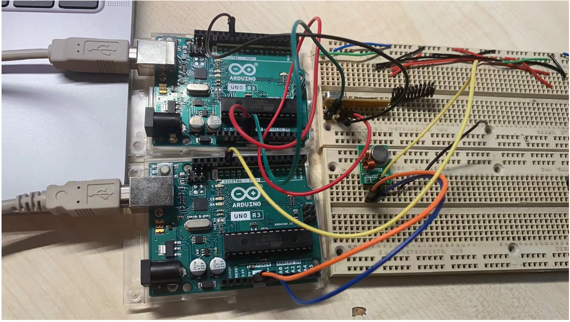
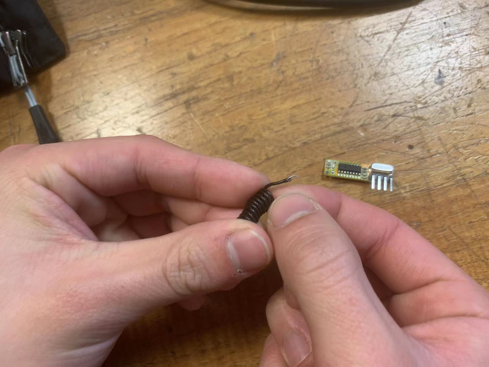
We placed the transmitter and receiver on two different Arduinos and used code to run the test. Figure 2 shows the test circuit. However, the serial monitor of the receiver can only receive information occasionally. After a series of tests, we confirm that the problem is due to poor contact between the coil and the board. After we removed the solder and welded them again as Figure 3 shows, the receiver worked well and Figure 4 shows the screenshot of the serial monitor of the receiver after sending "hello" in hexadecimal with the transmitter.
Figure 2. The test circuit of the transmitter and receiver
Figure 3. Resoldering the receiver
Figure 4. The screenshot of the serial monitor
Work in Week 4
1. Finish combining the code
2. Finish assembling the car and the glove
3. Run tests on expected functions


评论
发表评论