Week 4
24/02/2022
Attendance:
Yuang Du
Zhenhe Gao
Shibo Wang
Zhongning Wang
Dengwei Sun
Erxing Ren
Alessandro Pausilli
Process of Project
We firstly realized some auxiliary functions such as LED display and model switch. Then we finished the final hardware assembly of the car and controller. Finally, we combined the code and finished the function test, which lasted almost 5 days.
LED Display
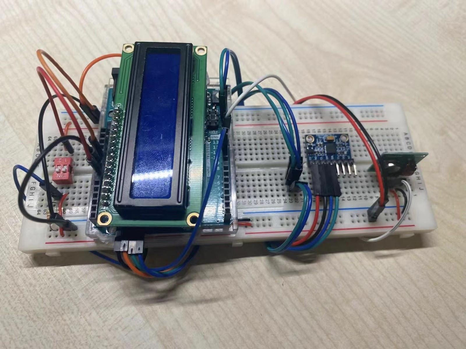
We managed to make a LED display work today, which will be equipped on the controller to display the calibration reminder and current model. The circuit is shown in Figure 1 in which "Hello, world" is printed on the screen.
Change the I2C
When the servo motor is used with the transmitter at the same time, the head file "Servo.h" is incompatible with "virtualWire.h", so we replaced "Servo.h" with "ServoTimer2.h".
Mode Switch
A switch is equipped on the controller to control the power supply and convert the model of motion. As Figure 2 and Figure 3 show, when switch 2 is on, the transmitter will transmit "2" to the receiver. As Figure 4 and Figure 5 show, when switch 2 is off, the transmitter will transmit "1" to the receiver.
Figure 2. Switch 2 is on
Figure 3. Serial Monitor when Switch 2 is on
Figure 5. Serial Monitor when Switch 2 is on
Car Assemble
The assembled car is as shown in Figure 6.
Controller Assemble
The assembled controller is as shown in Figure 7.
Model 1 Test
Two
of the pins on the Arduino board which control motors lost the analog property.
As a result, the speed variation under the control of these two pins can not be
realized. Due to the limited time, we have to give up the speed variation when running
backward. All other functions can be realized as expected. The function of model 1 is shown in Video 1.
Model 2 Test
As displayed in Video 2, the function of model 2 is realized. When the obstacle ahead is at a distance of more than 1m, the car will run relatively fast and slow down between 0.5m and 1m. When there is an obstacle within 0.5m, it will stop and make a turn after comparing the room on the left and right.
Video 2. Mode 2 display
Risk assessment:
1. The data transformation between the controller and the car is not stable enough. The car can only be controlled by the glove at a limited distance.
2. The
backward speed is obviously higher. After running a series of tests, it turns
out that two pins controlling moving backward can not do analog output, which
means when the car is moving backward, it is always moving at the highest speed
instead of the speed we want.
These two drawbacks are both hardware limitations.
By changing a more advanced communication component, for example, the Bluetooth module,
and changing another Arduino board with normally functioning analog pins, we
can actually solve them.


评论
发表评论